Sunday, October 8, 2017

NeoPixel RGB LED testing with Raspberry PI 3 without logic level shift

Recently, I learned that, there are RGB LEDs called NeoPixels with a kind of one wire interface built-in to change the colour of the LED by providing a specific clock signal. I quickly ordered a strip of 8 LED to try it out from ebay. I received it very quickly and the model number mentioned in the PCB is "CJMCU-2812-8".

As I was working with my Raspberry Pi 3 running Raspbian Stretch Lite for some other project, I wanted to test my NeoPixels with the same. After a bit of online research, I found out that many people have used level convertors to convert 3.3V logic of RPi3 to 5V logic of NeoPixels. Any how I wanted to try out the direct connection without any logic conversion with below options.

1. Powering up NeoPixels with 3.3V, so that the logic level will be the same as RPi3. Some posts from internet suggested that brightness will be reduced. As per my observation it is negligible.

2. Powering up NeoPixels with 5V, but connect RPi3 3.3V logic directly and hope for the best. But in my test setup, it worked perfectly without any issue.

The connection between RPi3 and NeoPixel PCB was straight forward when using the RPi3 library called rpi_ws281x.

GND -> GND
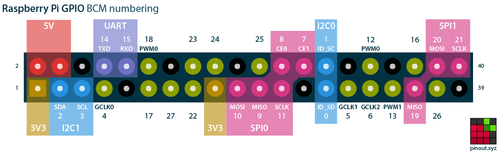
GPIO 18 (PWM0) -> DIN
5V or 3.3V -> 4-7VDC
GND -> GND

RPi Pin-out courtesy of pinout.xyz
RPi3 to NeoPixels PCB connection


You can follow up the detailed user manual of rpi_ws281x as a guide to install and use the library with Raspbian Stretch Lite. I used below commands in order to test.

Download and install the library

pi@raspberrypi:~ $ sudo apt-get update
pi@raspberrypi:~ $ sudo apt-get install build-essential python-dev git scons swig
pi@raspberrypi:~ $ mkdir neo
pi@raspberrypi:~ $ cd neo
pi@raspberrypi:~/neo $ git clone https://github.com/jgarff/rpi_ws281x.git
pi@raspberrypi:~/neo $ cd rpi_ws281x
pi@raspberrypi:~/neo/rpi_ws281x $ scons
pi@raspberrypi:~/neo/rpi_ws281x $ cd python
pi@raspberrypi:~/neo/rpi_ws281x/python $ sudo python setup.py install

Testing with standtest.py script

pi@raspberrypi:~/neo/rpi_ws281x/python $ cd examples
pi@raspberrypi:~/neo/rpi_ws281x/python/examples $ ls
lowlevel.py  multistrandtest.py  neopixelclock.py  SK6812_lowlevel.py  SK6812_strandtest.py  SK6812_white_test.py  strandtest.py
pi@raspberrypi:~/neo/rpi_ws281x/python/examples $ nano strandtest.py


Change parameter as below for my 8 LED strip then CTRL+X and then Y to save:


 pi@raspberrypi:~/neo/rpi_ws281x/python/examples $ sudo python strandtest.py
Press Ctrl-C to quit.
Color wipe animations.
Theater chase animations.
Rainbow animations.


This is the final result of my setup running standtest.py test script.

Sunday, September 28, 2014

Sinhala font installation on Sony Xperia V (Android)

You can install any Sinhala font from your mobile itself and use it in any browser you like with following instructions.

Preparation:

1) Root your device.
I rooted my Sony Xperia V (LT25i) with "towelroot" tool. No need to run complex scripts, just one click is enough.

2) Download a Sinhala ttf font to your phone and rename it to "DroidSansFallback.ttf" (or get a renamed file from here)
I have put this font file to "/sdcard1/DroidSansFallback.ttf" in the beginning.

3) Install a terminal emulator app from Google play store", I used this "terminal emulator"


Procedure:

Open the terminal emulator app and run the following commands in the given order.

1) Get root access
#su

2) Grant super user access to terminal emulator in the pop up window.

3) Get read/write access to /system
#mount -o rw,remount /system

4) Copy DroidSansFallback.ttf file /system/fonts
#cp /sdcard1/DroidSansFallback.ttf /system/fonts


Now you can open your favorite browser and read Sinhala text, I used Firefox browser to test it.


Monday, March 17, 2014

Experimenting Near Field Communication (NFC) with NXP MIFARE MF1S50 tags with Sony Xperia V

I have a Near Field Communication (NFC) capable Sony Xperia V mobile phone and I was able to communicate phone to phone.  Then, I found some cheap NFC tags on ebay which are based on NXP MIFARE MF1S50 chips. I got 5 tags for US$ 3.95 from this seller. They have free space of 716 bytes which can be used to store user data.


First you have to enable NFC at the android settings. Then, you can communicate with tags by placing them in the bottom of the mobile phone.


I used NFC TagInfo by NXP on Google play to identify the tags in the first place.


I was able to format the tags and write data to them using NFC TagWriter by NXP in Google Play.In this example, I'm going to write plain text "hello" to the NFC tag.


I was able to read the tag using the same application and also by using other applications such as NFC Tools.


Thursday, January 2, 2014

Gerber viewer for your Android mobile phone

When we are working with PCB fabrication systems, "Gerber" files are widely used as the input to the fabrication device from the CAD drawing. So, It is very useful to have a Gerber viewer on your mobile phone. Recenlty, I had to work with some microstrip designs and I had to check and compare the finished product at the fabrication facility. So, I found this free Gerber viewer at "Google Play" and you can find this at here. Here are some screeshots from this application showing a microstrip patch antenna in my mobile phone.


Interfacing sensors from Android mobile phone via Bluetooth

Most of the Android powered mobile phones have many in-built sensors. Android API gives us access to these sensors in API level without low level programming. Hence, we can use Bluetooth and these sensors to get sensor data to our embedded systems (may be for your robot). I modifed the "Blutooth Chat" application sample included in Android SDK to send accelerometer data via Bluetooth from my Sony Ericsson Xperia X8.


Modifying cheap servo motor for continuous rotation

You can buy cheap servo motors from ebay for a price of less than a gear motor. But these servo motors can't be used for continuous motion. A simple modification can be done by removing the locking mechanism as in the below photos. I'm using a metal geared servo motor from ebay for this. You should also glue the potentiometer in the middle postion after cutting the lock in the gear. You can use different pulses with varying pulse width and frequency to get continuous motion in the clock wise and anti-clock wise directions.


Tuesday, August 20, 2013

Ultrasonic distance measurement using HC-SR04 ultrasonic module + Arduino Pro

Ultrasonic sensors (Ping sensors) are widely used in distance measurement as they are cheap and has a quite good accuracy. I got this cheap HC-SR04 ultrasonic module from ebay and wanted to test it.
I found the datasheet for it from here.

According to the datasheet ;
Max Range = 400cm
Min Range = 2cm

This algorithm should be used to get the echo from the module:
1. Give 10uS pulse to the TRIGGER pin.
2. Measure the pulse width at ECHO pin.
3. Calculate  distance = (echo high level time×velocity of sound) / 2

I connected the module to my Arduino Pro (Techduino) and wrote a small code for the testing. The code will send the calculated distance value to PC via its UART port.


The code :

#define echo 8
#define trigger 9
long duration,distance;

void setup() {
 Serial.begin (9600);
 pinMode(trigger, OUTPUT);
 pinMode(echo, INPUT);
 digitalWrite(trigger, LOW);
}

void loop() {
 digitalWrite(trigger, LOW);
 digitalWrite(trigger, HIGH);
 delayMicroseconds(10);
 digitalWrite(trigger, LOW);
 duration = pulseIn(echo, HIGH);
 distance = duration/58;
 if ((distance >= 400) || (distance <= 2))
 distance = -1;
 Serial.println(distance);
 delay(60);
 
}
I checked the output from the Arduino to PC using a terminal program.


After that I coded a small software to get the distance data and show it in a nice way using Visual C#. This is my first C# application and I referred here and here for coding. You can download the source code and application from here.


Thursday, August 8, 2013

Computer controlled automated guided vehicles (AGV) using Parellel port interfacing

As we built a relay board to interface with "parallel port" in my earlier post. Today I'm going to talk about the control software for it. I wrote this software long time ago using Visual Basic 6 and inpout32.dll as the interface. I used this to control some modified toy cars as autonomous vehicles similar to automated guided vehicles (AGV). The path can be programmed to the software in realtime or in advance. So, the vehicle will follow the route as we need. You can download the program with source code from here.

The software interface:


This was first designed as a school science exhibition project in 2007 and recently used to control a mars rover model in a local astronomy exhibition at Sri Chandananda Buddhist College:


The mars rover model:


The control circuit:

RS-485 Communication testing with MAX485

As we know about RS-232 communication protocol, I'm going to try RS-485 communication between two nodes. RS-485 can support multiple slaves and mostly used in industrial applications with high separation distance between nodes. I recently got 10pcs of MAX485 IC from ebay for $1 which is a RS-485 transceiver. I also got  USB to RS-485 convertor based on CH430 + MAX485. I'm using another USB-UART convertor based on PL2303 for this test setup. So, I have two USB-UART chips connected using two MAX485 ICs in between,which provides the RS-485 communication.

My test setup according to MAX485 datasheet.
(Image extracted from datasheet)


As MAX485 is half duplex, I have to use one as TX with following setup. I'm using my USB-RS485 adapter as  RX and there is no need of manual setting as RX.


My TX setup on breadboard:


My RX setup, the one is right is USB-RS485 convertor:


Test results :

Tuesday, July 2, 2013

Writing and testing Linux kernel modules for Android

We compiled and installed some modules in Linux kernel in previous post. Here I'm going to write my own kernel modules and do the same. I'm stilling learning about this and I was able to write and test a hello world kernel module on my phone.

Phone kernel : Linux 2.6.32.60-Kappa1.6
PC O/S : Ubuntu 13.04 32bit
Cross compiler toolchain : Linaro GCC 4.7-2013.01

Prerequisite

1) Check for your kernel info using "uname -a" on either terminal emulator or ADB (use "adb shell" and run it).
My result:  Linux version 2.6.32.60-Kappa1.6 (Ka@Kappa) (gcc version 4.7.3 20130102 (prerelease) (Linaro GCC 4.7-2013.01) ) #94 PREEMPT Sun Apr 28 23:46:13 CEST 2013

2) Get the appropriate kernel source for your kernel. I got 2.6.32.60-Kappa1.6 kernel source from a GIT host using, (If you don't have git installed, you can install it by sudo apt-get install git)
git clone https://github.com/KaSt/Kappa.git
Now my kernel source is at /home/buddika/kernel/Kappa/

3) Download the appropriate cross-compiler toolchain, I'm using Linaro GCC 4.7-2013.01 toolchain.

4) Extract toolchain to somewhere, I extracted it to, /home/buddika/linaro

Coding

I made a directory for my coding as /home/buddika/modules
Please edit these codes to suite your environment. :)

1) hello.c

/* 
 *  hello-1.c - The simplest kernel module.
 */
#include <linux/module.h>    /* Needed by all modules */
#include <linux/kernel.h>    /* Needed for KERN_INFO */

int init_module(void)
{
    printk(KERN_INFO "Hello world 1.\n");

    /*
     * A non 0 return means init_module failed; module can't be loaded.
     */
    return 0;
}

void cleanup_module(void)
{
    printk(KERN_INFO "Goodbye world 1.\n");
}

2) Makefile

VERSION = 2
PATCHLEVEL = 6
SUBLEVEL = 32
EXTRAVERSION = .60Kappa-1.6

KERNEL_DIR=/home/buddika/kernel/Kappa/

obj-m := hello.o
PWD := $(shell pwd)
default:
    $(MAKE) ARCH=arm CROSS_COMPILE=/home/buddika/linaro/bin/arm-linux-gnueabihf- -C $(KERNEL_DIR) SUBDIRS=$(PWD) modules
clean:
    $(MAKE) -C $(KERNEL_DIR) SUBDIRS=$(PWD) clean

Building:

Now in console execute following commands,

cd /home/buddika/modules
make

Now the kernel module hello.ko will be built at /home/buddika/modules

Testing:

I copied /home/buddika/modules/hello.ko my sdcard at /sdcard/mymod using (please make /sdcard/mymod directory before doing this)
adb push /home/buddika/modules/hello.ko /sdcard/mymod/

You can log into phone shell using adb shell and get root access using su at the shell.

Let's load the module using,

insmod /sdcard/mymod/hello.ko

You can check whether the module is loaded by using lsmod and check for output


root@android:/ # lsmod
Module                  Size  Used by
hello                    610  0


Run dmesg and check for line like this.If so you have written your first kernel module and loaded it successfully. :)

<6>[29913.944610] Hello world 1.

References:
1) The Linux Kernel Module Programming Guide  
2) viulian's guide on xda-developers.com